A GLOBAL LEADER IN APPLIED ADDITIVE TECHNOLOGY SOLUTIONS
This white paper is probably not the first step in your 3D printing learning journey. By
now, you may have realized 3D printing is the solution for your design, prototyping and/
or production needs, since the advantages of 3D printing technology are widely known.
Driven by Computer-Aided Design (CAD), files that communicate directly with a 3D
printerand build a layered design from the bottom up, 3D printing technology provides
limitlesspossibilities. It enables nimble design iteration, rapid prototyping and the
ability to print production parts. With 3D printing’s capacity to revolutionize
FDM and PolyJet 3D Printing
D E T E R M I N I N G W H I C H T E C H N O L O G Y I S R I G H T F O R Y O U R A P P L I C AT I O N
FDM and PolyJet 3D Printing
D E T E R M I N I N G W H I C H T E C H N O L O G Y I S R I G H T F O R Y O U R A P P L I C AT I O N
industries, disrupt supply chains and lead
medical innovation, it’s no surprise the additive
technology has been described as the Third
Industrial Revolution.
The right 3D technology depends on the materials,
aesthetics, mechanical properties and overall
performance your product requires. You may have
already ruled out 3D printing technologies, such as
Selective Laser Sintering (SLS), Direct Metal Laser
Sintering (DMLS) and other processes, to arrive at
plastics as a material solution. Of course, that still
leaves the choice of Fused Deposition Modeling®
(FDM), or PolyJet™ technology, two of the most
advanced and versatile additive manufacturing
(AM) or 3D printing technologies available. This
white paper provides a detailed comparison of
Fused Deposition Modeling (FDM) and PolyJet
technologies and their applications within
different industries.
There is some crossover in FDM and PolyJet 3D
printer applications, but for the most part these
two technology platforms remain distinct and offer
different benefits to the user. Understanding the
two technologies and their application potential for
your product needs is the key to their successful
application within your business. Additionally,
the range of available printers goes from budget-
friendly, desktop models to large-format, factory-
floor equipment and produce precise, finely
detailed models to durable production goods.
Being fully informed about printer capabilities
and output, and matching a printer process and
material to your needs is the foundation to the
successful application of 3D printing within
your business.
THE TECHNOLOGIES
Fused Deposition Modeling (FDM)
3D printers that run on FDM technology build
parts layer-by-layer from the bottom up by heating
“The adoption of 3D printing as an engine for
growth and innovation is reaching levels where
the potential disruption is becoming very real.”
—Dr. Phil Reeves, VP, Stratasys Expert Services
FDM AND POLYJET 3D PRINTING / 2
FDM and PolyJet 3D Printing
D E T E R M I N I N G W H I C H T E C H N O L O G Y I S R I G H T F O R Y O U R A P P L I C AT I O N
and extruding thermoplastic filament. During pre-
processing, build-preparation software slices and
positions a 3D CAD file and calculates a path to
extrude thermoplastic and any necessary support
material. In production, thermoplastic filament
feeds through a heated head and exits, under high
pressure, as a fine thread of semi-molten plastic.
In a heated chamber, this extrusion process lays
down a continuous bead of plastic to form a layer.
Where support or buffering is needed, the 3D
printer deposits a removable material that acts
as scaffolding. This layering process repeats to
manufacture thermoplastic parts. Post-processing
involves the removal of support material, either
by manually breaking it away or dissolving it in
detergent and water. At this point, the part is ready
to use (Figure 1).
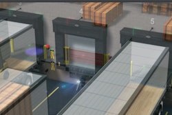
PolyJet Technology
PolyJet is a powerful 3D printing technology that
produces smooth, accurate parts, prototypes
and tooling. With microscopic layer resolution
and accuracy down to 0.1 mm, it can produce
thin walls and complex geometries. During
pre-processing, build preparation software
automatically calculates the placement of
photopolymers and support material from a 3D
CAD file. During production, a carriage with four
or more print heads and ultraviolet (UV) lamps
traverses the work space, depositing tiny droplets
of photopolymers, materials that solidify when
exposed to UV light. Fine layers accumulate on the
build tray to create one, or several, precise models
or parts. Where overhangs or complex shapes
require support, the 3D printer jets a removable
support material. After printing a thin layer of
material, the process repeats until a complete
3D object is formed. Support material is easily
removed by hand, with water or in a solution bath.
Models and parts are ready to handle and use
right out of the 3D printer, with no post-curing
needed (Figure 2). Certainly, employing both FDM
and PolyJet printers is an option. But in most
cases, one technology is better suited to your
product needs than the other. A comparison and
contrast of existing systems, operations, part
characteristics and material options is a good
place to start to determine how to best serve your
business needs.
Figure 1: Fused Deposition Modeling (FDM) process.
FDM AND POLYJET 3D PRINTING / 3
FDM and PolyJet 3D Printing
D E T E R M I N I N G W H I C H T E C H N O L O G Y I S R I G H T F O R Y O U R A P P L I C AT I O N
OPERATIONS
Speed
Build speed is an area of great interest to users;
however, there is no clear-cut answer as to which
technology is faster. Knowing your operations,
your parts and your requirements before
measuring speed is essential. Estimating one
process, FDM or PolyJet to be capable of quicker
build times can be very misleading. Some of the
variable elements of build time come from the
build styles you will use. High resolution, smooth
surfaces and solid parts with the best mechanical
properties will take more time. Build time is a
function of many variables, some you select and
others which are fixed. On average, FDM and
PolyJet have similar (and very competitive) total
elapsed times.
The detail of the parts and the height (since the
additive technology builds in layers from the
bottom up), contribute to overall build time. Printer
and file preparation adds time to the front end
while post-build idle (while waiting for the binder
to harden) and post-processing in the form of
cleaning, post-curing, de-powdering, support
removal, infiltration sanding or other steps add
time to the back end of production. In general, 3D
printer users typically fall into one of three build
patterns: four-hour cycles (half a workday), eight-
hour cycles (full workday) and overnight cycles.
Material volume, surface area and part footprint
and configuration can all add hours to the build
time. Also, to measure speed, one must clock
the entire process, starting with the moment an
STL file is received and stopped when a part is
ready for use. Along that path, a slower build time
still may outpace a process with a faster build
time which requires more post-processing. So, a
four-hour build plus the additional required steps
can result in a 12-hour process. Conversely, an
eight-hour build time plus other required steps can
result in only a 10-hour process. So, the process
with a slower build stage could be the overall
faster process (Figure 3).
Print speed alone should not drive your decision to
use FDM or PolyJet technology; the bigger picture
Figure 2: PolyJet technology process.
FDM AND POLYJET 3D PRINTING / 4
FDM and PolyJet 3D Printing
D E T E R M I N I N G W H I C H T E C H N O L O G Y I S R I G H T F O R Y O U R A P P L I C AT I O N
involves taking into account the geometry of parts,
and any support material needed in terms of post-
processing. Only after taking all these factors into
account can 3D printing build times be compared.
Time-to-Part Shortened
Piper Aircraft, a single and twin-engine jet
manufacturer wanted to reduce the time-to-part
for its hydroforming form tools, a process that
involves pressing sheet metal against the form
tool to force it to take its final shape. Piper uses
hydroforming to produce hundreds of aluminum
structural components of these aircraft such as
the inner frame, gussets, brackets and skins.
In the past, the company machined aluminum
form tools for use in hydroforming machines, but
found machining geometrically complex form
tools was expensive due to the amount of time
required for programming every part. As is often
the case, the material properties necessary for
their hydroforming process led engineers to FDM
technology. FDM printers offers unparalleled
versatility in durable parts. These parts are tough
enough to be used as advanced conceptual
models, functional prototypes, manufacturing
tools and production parts. In Piper’s case,
the material best suited to their needs was
Polycarbonate (PC), which can withstand
hydroforming pressures ranging from 3,000 to
6,000 psi, suitable for forming all the structural
parts produced by Piper (Figure 4).
Once the necessary material properties dictated
the best print technology, the jet manufacturer was
able to turn to other considerations, namely the
value of 3D printing to their operation, in general.
“I can program an FDM part in 10 minutes while
a typical CNC program takes four hours to write,”
said Jacob Allenbaugh, manufacturing engineer
for Piper. “The FDM printer is much faster than a
CNC machine and does not require an operator be
in attendance.”
Example 1
Example 2
Build Time (Hrs.)
Other Required Steps (Hrs.)
8
8
2
4
Figure 3: Build time steps from STL file to completion of part.
Figure 4: Hydroformed parts at Piper Aircraft using FDM technology.
FDM AND POLYJET 3D PRINTING / 5
FDM and PolyJet 3D Printing
D E T E R M I N I N G W H I C H T E C H N O L O G Y I S R I G H T F O R Y O U R A P P L I C AT I O N
In addition to faster time-to-part, the company
looked to FDM technology to satisfy its need for a
large build envelope and a high level of accuracy.
After forming, the route and drill fixtures are used
as a guide for routing and drilling operations that
finish the part. An added benefit of FDM to Piper
is the ability for future design improvements in
structural parts. With no limit to geometries of
finished parts, Allenbaugh believes it may be
possible to build a more efficient aircraft by
moving to more complex and organically shaped
parts, built with FDM form tooling.
Volvo Construction Equipment (VCE), tasked
its engineering team with cutting development
costs and reducing the lead time on large engine
projects from 36 to 24 months. VCE looked to 3D
printing, but wondered if 3D printed water pump
housings could withstand functional testing.
FDM technology was not the answer, but PolyJet
was thanks to its wide array of materials, even
transparent ones. Water pump housing prototypes
need to survive the high pressure of the engine
compartment. Engineers printed the housing in
FullCure®720, a transparent material, mounted
nine threaded inserts into the part and sealed the
housing with epoxy resin and hardener to prevent
leakage. Then they fastened the housing to a
water pump so engineers could take water flow
and pressure measurements (Figure 5).
PRE-PROCESSING:
WHAT’S INVOLVED
FDM
In GrabCAD or Catalyst software, a CAD file
is opened in STL format. Next, material, color
and slice thickness is selected. Then, a build
and support style is chosen to match your
application’s requirements. Finally, an orientation
is selected, and the software takes over from
here. The software sections the design into layers
and creates toolpaths for both the part and its
disposable support structures. It then outputs
a build file that defines precise motion control
paths. Clicking “print” sends the build file to the
3D printer.
Both technologies offer very simple, front-end
file processing that can make ready-to-print files
in less than five minutes. One difference is that
FDM’s production 3D printers add sophisticated
Figure 5: Water pump prototype at Volvo Construction Equipment, 3D
printed using PolyJet technology.
FDM AND POLYJET 3D PRINTING / 6
FDM and PolyJet 3D Printing
D E T E R M I N I N G W H I C H T E C H N O L O G Y I S R I G H T F O R Y O U R A P P L I C AT I O N
user controls that adjust the part-building process
to match the demands for the application. All build
parameters are open to the user. Both FDM and
PolyJet can print parts within 10 minutes of a
file upload.
PolyJet
PolyJet 3D printing works similarly to inkjet
printing but instead of jetting drops of ink onto
paper, PolyJet 3D printers jet layers of curable
liquid photopolymer onto a build tray. During
pre-processing, build-preparation software
automatically calculates the placement of
photopolymers and support material from a
3D CAD file.
POST-PROCESS
When it comes to support removal and part
cleaning, there are some similarities between
FDM and PolyJet. With FDM, you have either a
fully automated soak in a tank to remove soluble
supports or a manual step that removes rigid,
breakaway supports with simple hand tools.
PolyJet gives you a quick, manual step to remove
the gel-like support material SUP705 by spraying
with a WaterJet. In addition, SUP706, a soluble
support material for PolyJet technology, runs on
all triple-jetting 3D printers and requires a simple
two-step soak-and-rinse process like FDM.
When speed is paramount, SUP706 can also be
removed semi-manually or manually and washed
away easily with a WaterJet.
SUP706 enables increased geometric freedom,
giving users the ability to print complex, delicate
features and small cavities with PolyJet.
PolyJet parts require no post-printing curing and
little effort for support removal.
The Jacobs Institute (JI), a medical device and
leading vascular center in Buffalo, New York, uses
PolyJet 3D printing technology for patient-specific
models based on CT and MRI scans. These
models represent a patient’s unique vascular
anatomy, enabling surgeons to not only plan and
practice a surgery before getting into the operating
room, but also to serve as patient reference points
before complex procedures (Figure 6).
Figure 6: The Jacobs Institute 3D prints vascular models using Agilus30
material and PolyJet technology.
FDM AND POLYJET 3D PRINTING / 7
FDM and PolyJet 3D Printing
D E T E R M I N I N G W H I C H T E C H N O L O G Y I S R I G H T F O R Y O U R A P P L I C AT I O N
Post-processing of these thin-walled vasculatures
can be tricky and time-consuming. Support
material needs to be extinguished from the narrow
arterial openings of these delicate models. PolyJet
technology, with its option for clear, rubber-like
materials that can withstand 30-50 device tests
prior to degrading has been the answer for the JI.
Initially using TangoPlus, a clear, rubber-like Digital
Material, the JI sought a material whose strength
would eliminate post-processing tearing. In
partnership with Stratasys, the JI is now working
with Agilus30, a clear Digital material, to be used
as an adjunct material.
The JI is pioneering the development of 3D
printed neurovascular models using PolyJet to
accelerate the development of new devices and
improve physicians’ ability to treat cerebrovascular
diseases such as strokes and aneurysms. These
3D printed models provide anatomically and
physiologically accurate models of the vasculature
within a patient’s brain, using PolyJet technology.
Office Environment
Both FDM and PolyJet require very little in the
way of special requirements, no sealed-off labs
and OSHA respiratory protection requirements.
All systems need only minimal plumbing and
electrical work and there is no airborne powder
produced by either process. Power and access to
water and drain tiles (for post-processing work) is
all that is required.
Additionally, both FDM and PolyJet come in office-
friendly sizes. The only exception is the Fortus®
900mc™ and Objet®1000™, which have large
footprints and require a large work area.
Ease of Use
Both processes, FDM and PolyJet are relatively
user-friendly, beginning with the simplicity of file
setup. Other benefits are:
• Material changeovers: simply remove one
material and slide a new material cartridge into
the 3D printer.
• Setup for a build: insert a build sheet (FDM only),
bring the system up to operating temperature,
push start and walk away.
• When complete: open the door/hood and
remove parts just seconds after a job completes.
Operating Expense
Again, both processes have their own budgetary
perks and limitations. Overall, however,
operating expenses are a bit higher for PolyJet.
Consumables, or materials, are the largest
operating expense with additive manufacturing,
FDM AND POLYJET 3D PRINTING / 8
FDM and PolyJet 3D Printing
D E T E R M I N I N G W H I C H T E C H N O L O G Y I S R I G H T F O R Y O U R A P P L I C AT I O N
both in hardware and materials, and PolyJet
materials are more costly than FDM.
PolyJet: PolyJet print heads require replacement
after 2,000 hours (or more) of PolyJet 3D printing.
The total material cost per cubic inch of part is
less with FDM. In the cartridge, the technologies
have comparable material costs by weight. Yet,
FDM has a lower cost per part because it needs
only minimal support material. PolyJet systems
need more support material to restrain the tiny
liquid droplets.
FDM: Build trays or sheets need routine
replacement as do extrusion nozzles. The material
cost per cubic inch of part is less with FDM, and
FDM has a total lower cost per part because it
needs only minimal support material.
Utah Trikes, a custom-producer of trikes, quads
and custom wheelchairs located in Payson,
Utah, quickly realized their customization had
its obstacles, namely time and cost. The trike
manufacturer “had some CNC machines we ran
pretty much nonstop,” said Ashley Guy, president
and CEO. “But this was always a hassle without
committing to jigs and fixtures, which meant a lot
of man hours to prototype.”
Utah Trikes needed not only a process that could
be quick and cost-effective, but also one with
materials strong enough to go from prototype
to production parts. With 3D printing and FDM
technology, Guy said, “I no longer have to
constrain my designs because of prototyping
limitations.” Their ability to custom print, on-site
cut production time from two months to two
weeks, reducing the company’s costs 8-10 times.
The trike manufacturer started using FDM Nylon
12™ on its Stratasys Fortus 3D Printer, “and it
got us about 75% of the way there,” said Guy.
As the manufacturer moved to production grade
parts needing excellent strength they looked to
FDM Nylon 12CF™ to provide “parts that can be
printed faster, with superior stiffness-to-weight
performance and with better repeatability than
any other 3D printing technology we’ve seen,” said
Guy. Again, in the case of Utah Trikes, material
properties dictated print technology (Figure 7).
Figure 7: Utah Trikes uses FDM Nylon 12CF material in its advanced
prototyping.
FDM AND POLYJET 3D PRINTING / 9
FDM and PolyJet 3D Printing
D E T E R M I N I N G W H I C H T E C H N O L O G Y I S R I G H T F O R Y O U R A P P L I C AT I O N
PART CHARACTERISTICS
Surface Finish
If a near-paint-ready surface, or flexibility is your
goal, then PolyJet is your process. With a little
wet-sanding and polishing it can deliver a smooth,
glossy surface ready for any product that requires
no surface imperfections. PolyJet technology
enables parts and prototypes with the best
surface quality, finest details and widest range of
material properties available.
FDM is produced with an extrusion process that
leaves visible layer lines on side walls and “tool
paths” on the top and bottom surfaces. These
can be eliminated but this requires additional
post-processing, such as an automated finishing
station or manual finishing. Still, FDM technology
uses production-grade thermoplastic and builds
strong, long-lasting and dimensionally stable parts
with the best accuracy and repeatability of any 3D
printing technology.
Mikkelsen Electronics, in Denmark, develops
customized cable and molding industry solutions.
The company invested in 3D printing to reduce
production time and cost, and to offer affordable
prototypes. “We have long been focused on
the customer’s value chain with regard to low-
pressure molding,” said Kim Christiansen,
CEO of Mikkelsen.
FDM is the company’s technology of choice due
to its ability to 3D print precise parts that endure
high temperatures. Mikkelsen depends on FDM
thermoplastics that withstand high heat for long
periods of time. “The finished parts are fully
operational from the outset, giving us far greater
credibility with our customers,” said Christiansen.
Purchasing a Fortus 3D Printer from Stratasys,
Mikkelsen prints in both ABS thermoplastic and
ULTEM™ resin, depending on usage (Figure 8).
“Dialogue with customers has taken a completely
different, and very positive turn,” said Christensen.
“We now offer new features and we are monitoring
developments and focusing on developing our
products. Additionally, we are considered a more
serious player in the market.”
Brooks Running, in Seattle, Washington, just
may be the happiest place on earth, according to
Kenny Krotzer, associate footwear developer at
Figure 8: FDM’s low pressure molding capabilities made it the right 3D
printing process for Mikkelsen Electronics.
FDM AND POLYJET 3D PRINTING / 10
FDM and PolyJet 3D Printing
D E T E R M I N I N G W H I C H T E C H N O L O G Y I S R I G H T F O R Y O U R A P P L I C AT I O N
the company. “And this is due, in no small part,
to our Connex3™ 3D Printer,” Krotzer said. The
company “aims to build the best performance
product on the market and now we have a new
tool to help us get there.”
The large print bed on the PolyJet 3D Printer
enables Brooks to print four to five outsole,
midsole combination prototypes at a time,
something that greatly speeds their designs to
market. “There’s such freedom with having it, the
ability to set up a redesign to print overnight and
it’s ready in the morning.”
Frequent design iteration and designers and
shoe developers in China and the U.S. “used to
make for a bit of a nightmare,” said Krotzer. “Our
3D printer has revolutionized our entire design
validation process.” In addition to saving time
during the design iteration process, the
company also saves $500 to $800 per shoe
design (Figure 9).
Design validation is a huge component of the
business, according to Krotzer. Product fit and
functionality come first, but design is a close
second. “There’s a lot of give and take in shoe
design and the ability to quickly change a concept
is key.” Also, Brooks’ PolyJet technology enables
them to print dozens of colors “and while we only
need black, white and gray right now, that could
change someday,” said Krotzer.
Accuracy
For dimensional accuracy, the published
specifications show that comparable FDM and
PolyJet platforms have similar results for parts
when they are removed from the systems.
However, over time and under a load, FDM
materials are more dimensionally stable, which is
critical when used for production parts.
Size
Note: The following specifications have been
rounded for simplicity. For exact specifications,
refer to the product spec sheets.
PolyJet and FDM machines offer build volumes
ranging from 5 x 5 x 5 inches (127 x 127 x 127 mm)
to 39 x 31 x 20 inches (1000 x 800 x 500 mm),
and they have comparable mid and large-size
options. The difference is only in the small volume
category. With FDM, there is an entry-level 5 x 5 x
Figure 9: Brooks Running uses PolyJet technology to 3D print midsole
and outsole prototypes to expedite its design process.
FDM AND POLYJET 3D PRINTING / 11
FDM and PolyJet 3D Printing
D E T E R M I N I N G W H I C H T E C H N O L O G Y I S R I G H T F O R Y O U R A P P L I C AT I O N
5-inch option with a footprint small enough to sit
on a desktop.
PolyJet’s smallest is 9 x 8 x 6-inch (240 x 200 x
150 mm), and that 3D printer is best placed on a
stand near the work area.
For maximum part size, consider the orientation
in the 3D printer. For example, the two largest
machines, the FDM 900mc and the Objet1000,
have similarly sized build envelopes, but the tallest
part in the Fortus 900mc is 36 inches. The tallest
for the Objet1000 is 20 inches. The opposite is
true for width, the Fortus 900mc offers 24 inches
and the Objet1000 offers 31 inches.
Materials
Materials may be the greatest differentiator
between FDM and PolyJet processes for many.
Combined, there are thousands of options,
ranging from real thermoplastics to
thermoplastic-like resin, rigid to flexible, and
opaque to transparent.
PolyJet offers product realism across a wide
range of materials and colors. With over 1,200
color options available and a wide range of
Digital Materials (two or three materials blended
at the printhead), there are literally thousands of
available colors, in a range of hues, transparency,
strength, rigidity and flexibility. For example,
flexible, rubberlike parts can be printed with
Shore A hardness ratings of 27 to 95. Another
factor that contributes to product realism is multi-
material printing. Parts can have up to 82 distinct
material properties, so applications like flexible
overmolding of rigid structures can be reproduced
in one print job. Certainly, if a range of material
properties serves your needs, then PolyJet may be
your preferred platform.
Conversely, if your applications require real
thermoplastics with both functionality and
durability, FDM may be the correct platform
for you. Thirteen material options range from
commonly used plastics like ABS and ASA, to the
highly advanced, like ULTEM™ 9085 resin. Material
options include: anti-static, FST rating (flame,
smoke and toxicity), chemical resistance and
very high temperature resistance. FDM can
also make soluble patterns for challenging
manufacturing jobs.
Both FDM and PolyJet offer bio-compatible
materials with USP Plastic Class VI to ISO 10993
ratings. They can be used for hearing aids, dental
procedures, surgical guides and fixtures, and food
and pharmaceutical processing.
FDM AND POLYJET 3D PRINTING / 12
FDM and PolyJet 3D Printing
D E T E R M I N I N G W H I C H T E C H N O L O G Y I S R I G H T F O R Y O U R A P P L I C AT I O N
Additive manufacturing, in both FDM and PolyJet
processes, spans the concept, design and
production components of product development
in industries that range from medical
appliances to industrial goods. It is these
application-specific demands that ultimately
answer the question of which technology is best
suited for a particular need.
The State University of New York (SUNY),
New Paltz and its Stratasys-MakerBot Additive
Research & Teaching (SMART) Lab, has more
than 40 3D printers, including both FDM and
PolyJet. The SMART Lab is part of the Hudson
Valley Additive manufacturing center (HVAMC),
partnering with SUNY to provide 3D printing
learning and opportunities for students and
the community.
Perhaps the most interesting aspect of the
SMART Lab is students’ ability to not only gain
valuable experience using 3D printing, but also the
opportunity for students to be paired with local
businesses to problem-solve 3D printed solutions.
“It’s great for students to get an understanding
of what’s needed in the workforce and then get
the skill set they need in order to succeed,” said
Kat Wilson, assistant director of HVAMC. The
university has even designed a new minor around
the capabilities of their SMART Lab, Digital Design
and Fabrication, designed to teach students
how to use computer software and integrate that
knowledge into 3D printing.
Although not necessarily a typical student-
business partnership opportunity, the owner
of Lagusta’s Luscious, a local chocolate shop,
partnered with the lab to design a mold in the
shape of a human skull. Students scanned a skull
procured from the anthropology department, then
produced a digital file that could be used to 3D
print the mold, which was used to create realistic,
chocolate skulls for a party celebrating a popular
television show.
Students at SUNY learn to take their 3D printing
knowledge and partner with the local business
community. “When businesses have a need, we’re
able to say we have a student that’s great at this,”
Wilson said (Figure 10). In this case, 3D printing
in PolyJet technology, using VeroClear material,
ended up providing students and a local business
owner with a 3D printed solution that was both
efficient and cost-effective.
Figure 10: 3D printed skulls, a product of business partnering with
SUNY New Paltz’s 3D printing SMART Lab.
FDM AND POLYJET 3D PRINTING / 13
FDM and PolyJet 3D Printing
D E T E R M I N I N G W H I C H T E C H N O L O G Y I S R I G H T F O R Y O U R A P P L I C AT I O N
0 1 2 3 4 5 6
Process Time
Pre-process
post-process
Office environment
Ease of use
0 1 2 3 4 5 6
0 1 2 3 4 5 6
Rigid
Flexible
Durable
Transparent
High-performance
Bio-compatible
0 1 2 3 4 5 6
0 1 2 3 4 5 6
Surface finish
Feature detail
Accuracy
Size
0 1 2 3 4 5 6
POLYJET 3D
PRINTING
FUSED DEPOSITION
MODELING (FDM)
FDM AND POLYJET 3D PRINTING / 14
FDM AND POLYJET 3D PRINTING / 15
Summary
Benefits of PolyJet 3D Printing
PolyJet technology offers exceptional detail,
surface smoothness and precision. The process
creates smooth, detailed prototypes that convey
final-product aesthetics. This allows for accurate
molds, jigs, fixtures and other manufacturing
tools. Also, complex shapes and intricate details
and delicate features can be achieved. PolyJet
also incorporates the widest variety of colors and
materials into a single model for
unbeatable efficiency.
Benefits of FDM 3D Printing
FDM technology is clean, simple-to-use and
office-friendly due to supporting production-
grade thermoplastics that are mechanically and
environmentally stable. Complex geometries and
cavities that would otherwise be problematic
become practical with FDM technology. Also,
FDM technology uses the same tried-and-tested
thermoplastics found in traditional manufacturing
processes. For applications that demand tight
tolerances, toughness and environmental stability,
or properties like electrostatic dissipation,
translucence, biocompatibility, VO flammability or
FST ratings, FDM thermoplastics deliver.
STRATASYS.COM
HEADQUARTERS
7665 Commerce Way, Eden Prairie, MN 55344
+1 800 801 6491 (US Toll Free)
+1 952 937 3000 (Intl)
+1 952 937 0070 (Fax)
2 Holtzman St., Science Park, PO Box 2496
Rehovot 76124, Israel
+972 74 745 4000
+972 74 745 5000 (Fax)
ISO 9001:2008 Certified
© 2017 Stratasys Ltd. All rights reserved. Stratasys, Stratasys logo,FDM, PolyJet, Fortus 900mc, Objet 1000, SR-30, SR-100, SR-110, PC-ISO, ABS-M30i, ABS-ESD7, PPSF, PC, PC-ABS, ASA, ABS M30, ABSplus, ABSi, FDM Nylon 12, FDM
Nylon 12CF, SUP705, SUP706, Digital ABS, RGD525, Rigur, Durus, Vero, Tango, VeroDent Plus, Vero Dent, MED610, VeroClear and RGD720 are are trademarks of Stratasys, Inc. ULTEM™ is a registered trademark of SABIC or affiliates. All
other trademarks belong to their respective owners. Product specifications subject to change without notice. Printed in the USA. WP_DU_FDMvsPolyJet_A4_0917a
For more information about Stratasys systems, materials and applications, call 888.480.3548 or visit www.stratasys.com
A GLOBAL LEADER IN APPLIED ADDITIVE TECHNOLOGY SOLUTIONS