Supply pressure effect (SPE), also called inlet dependency, refers to a phenomenon in process lines for gas cylinders when the outlet pressure changes in relation to an inverse change in inlet pressure. When the inlet pressure decreases, the pressure at the outlet will increase. Conversely, when the inlet pressure increases, the outlet pressure will drop proportionally.
It can surprise even the most skilled fluid system operators when this happens because it is expected that as the gas cylinder pressure reduces, the outlet pressure would also decrease at the same time and vice versa. When this does not happen, the operator is often left wondering how to manage SPE in pressure-reducing regulators.
A regulator’s SPE is typically provided by the manufacturer and depicted as a ratio or percentage describing the change in outlet pressure per change in inlet pressure. For example, if a regulator is described as having a 1:100 or 1% SPE, for every 100 psi drop in inlet pressure, the outlet pressure will increase by 1 psi. The degree of outlet pressure variation for a regulator can be estimated with the following formula:
ΔP (outlet) = ΔP (inlet) x SPE
Unbalanced vs. Balanced Poppet Design in Spring-Loaded Regulators
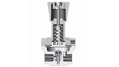
Regulators come in multiple varieties, but one of the most common in gas cylinder regulation is a spring-loaded pressure-reducing regulator (Figure 1). In this configuration, a spring pushes on either a diaphragm or piston to control the poppet over the orifice. In this way, it controls the outlet pressure. These regulators have either an unbalanced poppet design or a balanced poppet design.
 Figure 1. Inside a spring-loaded pressure-reducing regulator, a spring applies force on a sensing element to raise and lower the poppet over the orifice and thereby control the outlet pressure.Swagelok
An unbalanced poppet design allows the inlet pressure to push up on the poppet and exert force on the poppet equal to the seat area (Figure 2). Accordingly, a decrease in inlet pressure means less force is being put on the poppet. This allows the strong set spring to dislodge the poppet slightly further from the seat, resulting in an increase in outlet pressure. The pressure rise is not strong enough to entirely counterbalance the set spring force and allow the poppet to close in its original position. The resulting increase in outlet pressure can be attributed to SPE.
 Figure 2a. Inside this spring-loaded pressure-reducing regulator with an unbalanced poppet, the system media pressure – both at the inlet (FI), acting on the poppet seat area (A1), and outlet (FO), acting on the diaphragm – as well as the poppet spring force (FS2) keep the poppet shut when downstream valves are closed (2a). As flow is initiated downstream (2b), the outlet pressure (FO) drops, causing the set spring force (Fs) to flex the regulator’s diaphragm downward, opening the poppet to enable flow through the regulator. Because the inlet pressure (FI) pushes up on the entire surface area of the poppet seat area (A1), these regulators typically experience a greater degree of SPE than ones with balanced poppets.Swagelok
 Figure 2bSwagelok
The amount of SPE can be calculated using a ratio of areas on which pressures push on the poppet and sensing areas, since regulators perform using a balance of forces. In other words, regulators containing small sensing areas and large poppets will have the highest SPE, while those with small poppets and large sensing areas will have the lowest SPE.
To demonstrate the effect of an unbalanced poppet design on SPE, gradually decrease the inlet pressure. At an inlet pressure of 1160 psig (80 bar), the outlet pressure is 43.5 psig (3 bar). But when inlet pressure is decreased to 870 psig (60 bar), the outlet pressure jumps to 53.7 psig (3.7 bar). Since the inlet pressure acts on the entire surface of an unbalanced poppet, any change in inlet pressure produces a large change in force, driving a bigger shift in the balance of forces within the regulator.
In contrast, a balanced poppet design is frequently used to reduce SPE in high-flow applications because poppets are usually much larger in those applications. Under these circumstances, the goal is to minimize the area on which high inlet pressure can exert force (Figure 3). Designing a balanced poppet regulator allows the lower outlet pressure to reach the underside of the poppet through an orifice that runs vertically. The orifice is often sealed by an O-ring around the lower stem of the poppet. The changes in inlet pressure will not have as big an effect on the outlet pressure because it is acting on a much smaller area.
 Figure 3. This spring-loaded pressure-reducing regulator with a balanced poppet features an orifice in the poppet and a balancing O-ring, both of which reduce the poppet surface area in contact with inlet pressure (FI) to minimize SPE. Inlet pressure acts on only a small area, which is determined by subtracting the poppet base area (B2) – the balanced area – from the poppet area (A2), or A2 - B2. The orifice allows outlet pressure (FO), which is much lower than the inlet pressure (FI), to act on the bottom of the poppet (B2), minimizing and balancing the inlet pressure closing force (FI) applied to the poppet.Swagelok
To demonstrate how SPE impacts a balanced poppet regulator, envision gradually decreasing the inlet pressure as demonstrated previously with the unbalanced poppet design. Just as before, at an inlet pressure of 1160 psig (80 bar), the outlet pressure is 43.5 psig (3 bar). However, when inlet pressure is decreased to 870 psig (60 bar), the outlet pressure only increases to 46.4 psig (3.2 bar). In fact, even at an inlet pressure of 725 psig (50 bar), the outlet pressure continues to hold steady at 46.4 psig (3.2 bar).
What is notable here is that a balanced poppet regulator minimizes the effects of inlet pressure changes on outlet pressures. Balanced poppet regulators also reduce lockup, which is when a poppet snaps shut as downstream flow decreases to zero. Too much lockup can spike outlet pressures when the poppet suddenly closes.
Regardless of poppet design, however, SPE will always exist in gas system regulators. Even in situations where the poppet/valve closes slowly, SPE will happen. When an empty cylinder is changed for a full one, set outlet pressures will be different. Reducing the effects of SPE relies on making smart design decisions.
Two-Stage Pressure Reduction
SPE can be reduced in almost every application by using two-stage pressure reduction. To achieve this, operators can either install two single-stage regulators consecutively or combine regulators into one assembly (Figure 4). This can be preferrable in lower-flow applications such as analytical instrumentation systems. While single-stage regulators by themselves can control inlet pressure to some extent, a combined set of regulators help maintain the outlet pressure close to the original set point.
To calculate the variability of outlet pressure for a two-stage regulator setup, the inlet pressure difference is multiplied by the SPE of each regulator. This is illustrated in the following equation:
ΔP (outlet) = ΔP (inlet) x SPE1 x SPE2
It is important to emphasize that SPE demonstrates an inverse relationship between inlet and outlet pressures. What that means is that the first-stage regulator will be dealing with an increase in outlet pressure as the gas cylinder empties because the inlet pressure is decreasing, which will be passed on to the second-stage regulator. In practice, that will lead to a decrease in pressure on the outlet valve of the second regulator. Since the pressure reduction at the first-stage regulator is so large at the inlet, the outlet pressure change is smaller. As a result, the second-stage regulator has a much smaller pressure change at the inlet, which means the change at the outlet valve is minimal. Once the inlet pressure is reduced below the set pressure of the first-stage regulator, the system will behave like a one-stage regulator system.
To demonstrate supply pressure effect, consider a gas cylinder emptying from 2500 psig (172 bar) to 500 psig (34 bar) with a two-stage pressure-reducing regulator used to control downstream pressure. Assume that each regulator in the assembly has a 1% SPE. With a 2000 psig (137 bar) inlet pressure drop, the first-stage regulator will experience a 20 psig (1.3 bar) increase in outlet pressure. As a result of that increase, the second-stage regulator will only experience a 0.20 psig (0.01 bar) decrease in outlet pressure. Notice how the effect on the outlet pressure is dramatically much lower than the previous regulator arrangements.
Generally, a two-stage regulator setup will result in better SPE control than a single pressure-reducing regulator with a balanced poppet. In situations in which one gas cylinder is used for multiple operations and the outlet pressure does not change, operators may use either option. But for applications in which gas cylinders supply multiple operations at different pressures, two single-stage regulators are the preferred method of creating a two-stage regulator system. In this instance, operators should place the first-stage regulator close to the gas cylinder and the second-stage regulator on the process lines or at the point of use. Three-stage regulation, with a two-stage regulator at the gas cylinder and a single-stage regulator at point of use, is unnecessary in most cases.
The Benefits of Engineered Gas Distribution Systems
Another way to reduce SPE is to use a fully assembled and tested gas distribution system, which are modular subsystems that are specifically designed and configured for particular applications. These systems should include:
- A source inlet module or source inlet panel, which establishes a connection between the high-pressure gas source and the distribution system
- A gas panel, which completes the first pressure reduction of the source gas and ensures it is delivered at the correct flow rate to the next stage of the system (This is the part of a gas distribution system where SPE can best be controlled.)
- An automatic changeover system, which switches from one gas source to another to ensure uninterrupted supply
- A point-of-use system, which provides a final stage of pressure control prior to gas being used
Managing SPE Takes Proper Planning
Regardless of which regulator is used to control outlet pressure from gas cylinders, SPE will be present because a change in inlet pressure will always result in a change in outlet pressure. The goal is to reduce SPE to acceptable levels in applications by using a single-stage regulator with a balanced poppet design, a two-stage regulator, or fully configurable gas distribution systems. If the gas cylinder is supplying multiple operations with different pressure requirements, it may require several single-stage regulators – one near the gas source and one on each process line – or the use of preassembled gas distribution subsystems that can perform equally effectively.
Deciding which regulator or configuration is appropriate for a specific application is not a decision you should have to make on your own. Partnering with the right supplier that can offer expertise on gas distribution systems should provide you with the support you need to choose the proper regulator to reduce SPE and help your system run at peak performance.
An original version of this article appeared on the Swagelok Reference Point blog here: swagelok.com.
---
Shaji Arumpanayil is a product manager for Swagelok Company